Business License
Stamped Electrical Terminals: A Complete Guide to Materials, Tolerances, and Sourcing
Stamped electrical terminals are precision-formed metal components that create reliable electrical connections in automotive, electronics, power supply, and telecommunications equipment. They are produced by feeding conductive strip material through stamping dies that cut, pierce, bend, and form the terminal shape in high-speed, repeatable cycles.
A poorly specified terminal can increase resistance, overheat, or fail under vibration. The right terminal, built with the correct material and tooling, keeps current flowing and assemblies connected for the life of the product.
If you are sourcing custom stamped electrical terminals for connectors, busbars, switches, or circuit assemblies, this guide explains what drives performance, how the stamping process works, and what to look for in a manufacturing partner.
Key Takeaways
Copper and brass alloys dominate electrical terminals because conductivity, spring force, and corrosion resistance must match the application.
Progressive die stamping is the most efficient process for medium-to-high volume terminal production, holding tight tolerances across millions of cycles.
Terminal performance depends on edge quality, plating thickness, bend radius, and contact force, not just raw material cost.
In-house mold design and manufacturing shorten lead times and protect design intent for custom terminal geometries.
Always validate terminals with sample parts, dimensional reports, and plating certificates before committing to mass production.
What Are Stamped Electrical Terminals?
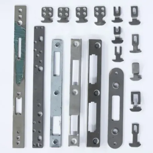
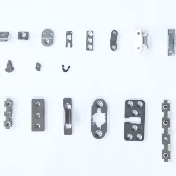
Stamped electrical terminals are small conductive components made from flat metal strip. They include fast-on terminals, ring terminals, spade terminals, pin headers, socket contacts, PCB terminals, and custom connector contacts. Each terminal performs one or more electrical or mechanical functions: carrying current, making contact with a mating part, securing a wire, or mounting to a housing.
The stamping process uses a punch-and-die set to transform coil stock into finished terminals. Operations include blanking the outer profile, piercing holes or slots, forming wire-crimp barrels, bending contact beams, and creating retention features. For complex terminals, progressive die stamping carries the part through multiple stations in one continuous die. Each station adds a feature until the terminal separates from the carrier strip.
Because terminals are often the smallest component in an electrical assembly, their geometry must be precise. A contact gap that is too wide reduces connection force. A crimp barrel that is too narrow damages wire strands. A burr on the mating surface increases contact resistance.
These details make terminal stamping a precision discipline, not a commodity cutting operation.
Common Terminal Types
Understanding terminal types helps buyers and engineers specify the right part:
Ring and spade terminals connect wires to screws or studs and are common in automotive and industrial power applications.
Fast-on or quick-disconnect terminals slide onto male tabs for rapid assembly in appliances and automotive harnesses.
Pin and socket terminals form removable connections inside plastic housings for electronics and connectors.
PCB terminals mount directly to printed circuit boards and provide solderable or press-fit connection points.
Busbars and distribution terminals carry higher currents and distribute power across multiple connection points.
Each type places different demands on material thickness, conductivity, spring characteristics, and plating.
Why Material Selection Matters for Electrical Terminals
The material determines how well a terminal conducts electricity, resists corrosion, maintains spring force, and survives assembly. Copper and brass alloys are the most common choices because they balance conductivity, formability, and cost.
Copper Alloys
Copper alloys are the foundation of most copper stamping components. Pure copper offers excellent electrical conductivity, often above 100% IACS (International Annealed Copper Standard). However, pure copper is soft and may not hold spring force well. For terminals that need both conductivity and mechanical resilience, copper alloys such as bronze, beryllium copper, and phosphor bronze are preferred. These alloys add strength while keeping conductivity within an acceptable range.
C11000 electrolytic tough pitch copper is widely used for copper stamping components where conductivity is the top priority. C51900 phosphor bronze and C17200 beryllium copper are common when spring properties and fatigue resistance matter more than maximum conductivity.
Brass Alloys
Brass alloys are also widely used for copper stamping components. Brass, an alloy of copper and zinc, is easier to stamp and often less expensive than high-copper alloys. C26000 cartridge brass is a common choice for terminals that do not carry extremely high currents. Brass accepts plating well and provides good corrosion resistance in indoor and controlled environments.
The trade-off is lower conductivity than pure copper or bronze. Engineers specify brass when cost, formability, and moderate conductivity are acceptable.
Material Thickness and Strip Width
Terminal performance also depends on material thickness. Thinner strip reduces material cost but may overheat under high current or lose mechanical strength. Thicker strip improves durability and current capacity but requires higher stamping force and larger bend radii. Strip width affects how many parts can be nested across the coil, which influences material utilization and per-part cost.
Engineering Note: Always match material thickness to current-carrying requirements and the terminal's mechanical load. Thinner material is not always cheaper when it causes field failures or derating.
The Electrical Terminal Stamping Process

Electrical terminal stamping and electrical connector stamping are typically produced by progressive die stamping, compound die stamping, or single-station operations. The choice depends on volume, complexity, and tolerance requirements.
Progressive Die Stamping
In progressive die stamping, the coil strip advances through a die that contains multiple stations. Each station performs one operation. The part remains attached to the carrier strip until the final station separates it. Progressive dies are ideal for high-volume terminal production. They complete complex parts in one press stroke at high speed.
Advantages for terminals include:
Tight dimensional repeatability across high volumes
Complex geometry in a single die, including holes, bends, and formed contacts
Efficient material utilization with optimized strip layout
Inline integration with plating, insertion, or packaging operations
For a typical automotive connector terminal, a progressive die might include stations for pilot holes, blanking, piercing, forming the wire barrel, forming the contact spring, and final cutoff.
Compound Die Stamping
Compound dies perform multiple cutting operations in a single station. They are useful for flat terminals where accuracy and clean edges matter more than complex forming. The trade-off is lower production speed and less design flexibility than progressive dies.
Secondary Operations
After stamping, terminals often require secondary operations:
Plating: Tin, nickel, silver, or gold plating improves solderability, corrosion resistance, and contact performance.
Heat treatment: Some copper alloys are heat-treated to optimize spring properties after forming.
Assembly: Terminals may be inserted into housings, taped on reels, or assembled into connector sets.
Inspection: Vision systems, continuity testers, and dimensional gauges verify critical features.
Tolerances and Quality Requirements
Electrical terminals operate in tight spaces. A terminal that is 0.05 mm too wide may not fit its housing. A contact beam that is out of spec may create an intermittent connection. Tolerance control is therefore central to terminal quality.
Typical Tolerances
Stamped terminal tolerances commonly fall within:
Blank dimensions: ±0.05 mm to ±0.10 mm depending on size and material thickness
Hole diameters and slots: ±0.03 mm to ±0.05 mm
Bend angles: ±1° to ±2°
Formed contact positions: ±0.05 mm to ±0.08 mm
Tighter tolerances are achievable with precision tooling and stable process controls, but they increase tooling cost and require more frequent inspection.
Burr and Edge Quality
Burr height affects assembly and electrical performance. A burr on a contact surface can create a high-resistance point or damage a mating terminal. A burr inside a crimp barrel can cut wire strands. Progressive dies with proper punch-and-die clearance, sharp cutting edges, and consistent strip guidance keep burrs within acceptable limits.
Standard terminal specifications often require burr height below 10% of material thickness, and sometimes below 5% for critical contact areas.
Plating Specifications
Plating thickness must meet the application environment:
Tin plating: Common for solderable and crimped connections; typical thickness 1–3 µm.
Nickel underplating: Used as a diffusion barrier and for corrosion protection.
Silver plating: Used for high-current or high-temperature applications.
Gold plating: Used for low-voltage, low-current, or high-reliability signal contacts.
Plating adhesion, thickness uniformity, and solderability should be validated with sample testing before mass production.
Mini-Story: When a 0.1 mm Gap Stopped a Production Line
In early 2025, a buyer named Elena at an automotive electronics supplier approved a batch of connector terminals based on a low unit price. The terminals looked correct in photos. When they arrived, the contact beam was 0.1 mm wider than the drawing specified.
That small difference prevented the terminals from seating properly in the plastic housing. Assembly line operators had to hand-trim parts, slowing output by 40%. By the time the issue was escalated, the supplier had already shipped 80,000 pieces. Elena spent six weeks qualifying a replacement batch and absorbing expedited air freight. The cheapest quote became the most expensive decision of the quarter.
This scenario illustrates why terminal sourcing cannot rely on price alone. Dimensional reports, sample approvals, and stable tooling control are essential.
Designing Terminals for Manufacturability
Design for Manufacturability (DFM) helps engineers create terminals that perform well and cost less to produce. Small geometry choices can make stamping easier, faster, and more reliable.
Keep Inner Radii Generous
Sharp internal corners concentrate stress and increase tooling wear. Generous radii improve material flow during forming and reduce the risk of cracks in copper alloys.
Avoid Extreme Aspect Ratios
Very narrow slots, long thin beams, or tiny holes near edges can be difficult to stamp consistently. When features are unavoidable, discuss alternative process sequences with the tooling engineer.
Specify Plating Clearly
Plating callouts should include base material, deposit material, thickness range, and any required testing standards such as ASTM B545 for tin plating or MIL-G-45204 for gold. Vague plating requirements create risk.
Design for Strip Utilization
Terminals are nested on a strip to minimize scrap. Symmetrical or repeatable profiles improve nesting efficiency and lower material cost. The strip layout is often optimized during mold design.
Want to reduce cost without sacrificing performance? Request a free DFM review and our engineering team will review your terminal drawing for manufacturability.
How to Choose a Stamped Terminals Manufacturer
Not every stamping supplier has the right capability for precision electrical terminals. The right stamped terminals manufacturer combines progressive die expertise with material knowledge, plating coordination, and quality systems.
In-House Tooling Capability
Terminal geometry is controlled by the die. A supplier that designs and builds molds in-house can iterate faster, protect confidentiality, and maintain tooling without relying on external shops. This directly affects lead time and lot-to-lot consistency.
Material and Plating Relationships
The supplier should understand copper and brass grades, including how each alloy behaves during stamping and plating. Strong relationships with plating houses ensure consistent finish quality and traceability.
Inspection and Validation
Look for suppliers that provide:
Dimensional inspection reports with critical dimensions
Material certificates showing alloy, temper, and conductivity
Plating thickness test reports
Sample approval lots before mass production
Corrective action processes for out-of-specification parts
Capacity and Scalability
A supplier with sufficient press capacity and workforce stability can support both prototype runs and high-volume programs. Ask about equipment count, facility size, and experience with terminal programs similar to yours.
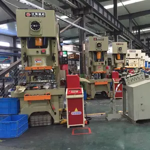
Cangzhou Honglang designs and manufactures molds in-house. We operate more than 100 sets of stamping machinery across a 10,000-square-meter facility. We supply electrical hardware stamping components to automotive, electronics, power supply, and telecommunications markets. Our engineering team of 20 technical professionals supports customers from material selection through sample validation and mass production.
Applications of Stamped Electrical Terminals
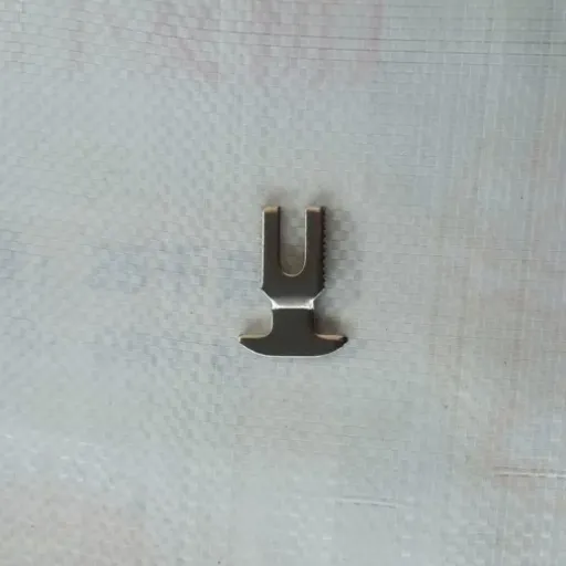
Stamped electrical terminals appear across industries where reliable current flow and compact connections are required.
Automotive Electronics
Modern vehicles use thousands of terminals in control modules, sensors, lighting, and battery systems. Automotive terminals must survive vibration, temperature cycling, and salt spray. Common finishes include tin and silver plating with nickel underlayers.
Consumer and Industrial Electronics
PCB terminals, pin headers, and socket contacts connect circuit boards, power supplies, and interface modules. These terminals often require tight pitch control and gold or tin plating for solderability.
Power Supply and Distribution
Busbars, fuse terminals, and distribution blocks carry higher currents. They require thicker material, larger contact areas, and plating that resists oxidation under load.
Telecommunications and Renewable Energy
Telecom and renewable energy equipment use terminals in cabinets, inverters, junction boxes, and power distribution units. These applications value long-term reliability and material traceability.
Mini-Story: Switching to a Single Supplier Cut Lead Time by Three Weeks
Marcus, a procurement manager at a power supply manufacturer, was splitting terminal sourcing between one stamping shop and a separate plating vendor. Tooling changes took two weeks to coordinate. Quality disputes dragged on because each supplier blamed the other.
After moving the program to Cangzhou Honglang, the terminal, plating, and inspection stayed under one roof. Engineering adjusted the strip layout to reduce scrap. The first article samples arrived in 10 days. Production lead time dropped from five weeks to two weeks, and lot-to-lot variation fell sharply.
Single-source accountability does not just reduce admin work. It removes the gaps where errors hide.
Cost Drivers for Custom Stamped Terminals
Understanding cost drivers helps engineers and buyers make better sourcing decisions for custom stamped terminals.
Tooling Cost
The progressive die is the largest upfront investment. Cost depends on terminal complexity, number of stations, material type, and required tolerance. Simple blanking dies may cost a few thousand dollars. Multi-station progressive dies for complex terminals can cost significantly more.
Material Cost
Copper and brass prices fluctuate with commodity markets. Material utilization, strip width, and part nesting directly affect how much metal is consumed per part.
Production Volume
Higher volumes reduce per-part cost because tooling investment is amortized over more pieces and high-speed stamping becomes more efficient. Low-volume runs may use simpler tooling or prototype dies to control upfront cost.
Plating and Secondary Operations
Each plating layer, heat treatment, or assembly step adds cost. Specifying only what the application requires avoids unnecessary expense.
Inspection and Documentation
Detailed inspection reports, material certificates, and PPAP documentation add cost but reduce risk for critical applications. Match documentation requirements to the actual needs of your end customer.
FAQ: Stamped Electrical Terminals
What materials are best for stamped electrical terminals?
Copper and brass alloys are the most common choices. Pure copper offers maximum conductivity. Phosphor bronze and beryllium copper add spring force and fatigue resistance. Brass provides a balance of cost, formability, and moderate conductivity. The best material depends on current, environment, and mechanical requirements.
How tight can stamped terminal tolerances be?
Typical terminal tolerances range from ±0.03 mm to ±0.10 mm depending on feature type, material thickness, and tooling precision. Tighter tolerances are possible but require more sophisticated dies and process controls.
What is the typical lead time for custom terminal tooling?
Tooling lead time usually ranges from 2 to 6 weeks depending on die complexity. Suppliers with in-house mold design and manufacturing can often deliver faster than those that outsource tooling.
Can plated terminals be stamped before plating?
Yes. Terminals are typically stamped first and then plated as a secondary operation. This sequence protects plating adhesion and ensures complete coverage of formed surfaces. Reel-to-reel plating is common for small terminals that remain on carrier strips.
What quality documents should I request before mass production?
Request dimensional inspection reports, material certificates, plating thickness reports, and sample approval records. For automotive or regulated applications, additional documentation such as PPAP or material traceability records may be required.
Conclusion
Stamped electrical terminals may be small, but they carry significant responsibility. Material choice, tooling precision, plating quality, and supplier capability all determine whether a terminal performs reliably for years or causes failures in the field.
The best sourcing decisions balance unit price with total cost of ownership. A terminal that costs slightly more per piece but arrives on tolerance, with full documentation and stable quality, is usually the better investment.
If you are developing custom stamped electrical terminals, start with a clear specification. Validate with samples, and choose a partner that controls tooling and production under one roof. Cangzhou Honglang welcomes the opportunity to review your drawing and provide a detailed quote with DFM feedback.
Recently Posted
-
Metal Stamping Design Guidelines: 7 Rules for Better Parts
August 4, 2026Good metal stamping design guidelines start with matching the part geometry to the right process, material, and tolerance expectat Read More
 -
Electrical Hardware Stamping Components: A Buyer’s Guide
August 3, 2026Electrical hardware stamping components are precision metal parts made from sheet metal or strip material. They include terminals, Read More
 -
Sheet Metal Prototyping Services: A Complete Guide for Product Development
August 3, 2026Sheet metal prototyping services help engineers and product teams validate designs, test fit and function, and refine manufacturin Read More
 -
Precision Sheet Metal Fabrication: An Engineering Guide to Tight-Tolerance Parts
August 3, 2026Precision sheet metal fabrication is the production of sheet metal parts held to tight dimensional tolerances, typically through c Read More

Contact Us
Recommended Products
-
 Custom Sheet Metal Fabrication: Laser Cutting, Stamping, Bending & Assembly ServicesNegotiableMOQ: 1 Piece
 -
Custom Precision Stainless Steel Metal Stamping Parts for OEM ApplicationsNegotiableMOQ: 1 Piece
-
Custom Automotive Metal Stamping – Stator Rotor Contact Clips for ElectronicsNegotiableMOQ: 1 Piece
-
High-Strength Sheet Metal Stamping for Motorcycle and Automotive ApplicationsNegotiableMOQ: 1 Piece
-
Galvanized Steel Custom Metal Deep Drawing Components Outdoor Deep Drawn Equipment Protective HousingNegotiableMOQ: 1 Piece
-
Professional Sheet Metal Stamping Process Service for Aluminum or Stainless SteelNegotiableMOQ: 1 Piece
-
Customized Stamping Parts for Furniture Auto Electrical Spring ContactsNegotiableMOQ: 1 Piece
-
Precision Custom Metal Deep Drawing Components Custom Sheet Metal Forming Fabrication ServiceNegotiableMOQ: 1 Piece
-
Custom Precision Deep Drawing Stamping Metal Components for IndustryNegotiableMOQ: 1 Piece
-
Stainless Steel Metal Stamping Components - Punching, Bending, Welding ServicesNegotiableMOQ: 1 Piece
-
Custom Deep Drawing Metal Stamping Components for Factory Construction MachineryNegotiableMOQ: 1 Piece
-
Ra0.4 Surface Roughness Metal Stamping Parts for Automotive Brackets PrecisionNegotiableMOQ: 1 Piece
-
Custom Stamping Parts Stamped Welded Deep Drawn Sheet Metal Fabrication ComponentsNegotiableMOQ: 1 Piece
-
Custom Stainless Steel Flat Leaf Spring – Metal Stamping PartsNegotiableMOQ: 1 Piece
-
Custom Sheet Metal Stamping Parts With Bending, Laser Cutting & Fabrication ServicesNegotiableMOQ: 1 Piece
-
Custom CNC Machined Sheet Metal Stamping, Bending, Welding, Laser Cutting & EDM Fabrication ServicesNegotiableMOQ: 1 Piece
-
Custom Precision Metal Stamping Parts High Tolerance Sheet Metal ComponentsNegotiableMOQ: 1 Piece
-
Custom Titanium Sheet Metal Stamping Parts Fabrication for Industrial UseNegotiableMOQ: 1 Piece
-
Durable Custom Metal Deep Drawing Components Surface Treated Forming Components for Construction Engineering EquipmentNegotiableMOQ: 1 Piece
-
China Manufacturer Custom Metal Deep Drawing Components Custom Sheet Metal Deep Drawing FabricationNegotiableMOQ: 1 Piece